Electrical
Theory & Applications for HVACR
Turner L. Collins
Earl Delatte
Randy F. Petit, Sr.
With the majority of HVACR service calls being
electrical in nature, it is important for technicians to have a
solid understanding of electrical fundamentals allowing them to
develop a systematic and methodical procedure for troubleshooting.
The
Electrical Theory and Application for HVACR manual provides
students and practicing technicians with the information and
knowledge necessary to accurately diagnose and solve electrical
system faults.
This manual is full of color illustrations and
includes student worksheets. The spiral binding will allow students
to tear out worksheets for grading by an
instructor if used in a Training environment.
Main topics include: safety and hazard
awareness, electrical fundamentals, circuits and components, motors,
wiring diagrams, automated control systems, and troubleshooting.
Contents:
Safety
and Hazard Awareness
-
Electrical Shock
-
Lockout‐Tagout Procedures
-
Do not Work Alone
-
Learn First Aid
-
Electrical Burns
-
Portable Electric Tools
- Non‐Conducting Ladders
- Safety Guidelines
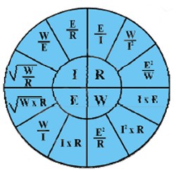
What is Electricity?
- Electrons
- Ohm's Law
- Potential Difference
- Inductive Reactance
- Volts
- Capacitive Reactance
- Measuring volts
- Impedance
- How Electrons Move
- Measuring Resistance
- Amperage
- Wattage
- Resistance
 Circuits
and Their Components Circuits
and Their Components
- Series Circuit
- Circuit Protection
- Total Resistance in a
Series Circuit
- Loads and Switches
- Series Circuit Laws
- Transformers
- Parallel Circuits
- Low‐Voltage
Transformers
- Total Resistance in a
Parallel Circuit
- Solenoid valves
- Parallel Circuit Laws
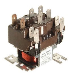
- Relays
- Combination Series
/Parallel Circuits
- Sequencer
- Three‐Phase Circuits
- Contactors
- Single‐Phase Circuits
- Contactor Coil
Burn‐Out
- The Neutral Wire
- Line Starters
- The Safety Ground Wire
- Defrost Timers
- Conductors
- Thermostats
- Insulators
- Heat Anticipators
- Semi‐Conductors
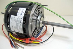
Motors
-
Induction Motors
-
The Run Capacitor
-
Parts of a Motor
-
Capacitor Ratings
-
Stator Poles
-
Single‐Phase Motor
Starting Relays
-
Stators
-
Current Relay
-
Rotors
-
Potential Relay
-
Motor Speed
-
Solid State and PTC
-
Shaded Pole
-
Calculating Motor
Horsepower
-
Split‐Phase Motors
-
Service Factor
-
Direction of Rotation
-
Locked Rotor Amps
-
Disconnecting the Start
Winding
-
Full Load Amps
-
CS or CSIR Motors
-
Overload Protectors
-
PSC Motors
-
Three‐Phase Motors
-
CSR Motors
-
Changing the Rotation of
a Three‐Phase Motor
-
Identifying Hermetic
Motor Terminals
-
Checking Resistance of
Windings
-
Electronically
Communicated Motors (ECM)
-
Dual‐Voltage Three‐Phase
Motors
-
Shaded Pole and PSC
Motor Speeds
-
The Motor Name Plate
-
Capacitors Name Plate
Data
-
Definitions
-
Start Capacitors
-
Variable Frequency
Drives
Understanding Wiring
Diagrams
-
Pictorial and Schematic
Diagrams
-
Ladder Diagrams
-
Pictorials versus
Schematics
-
Reading a Wiring
Schematic
-
Combining Pictorial &
Schematic Drawings
-
Schematic Diagram
Symbols
-
Line‐Side versus
Load‐Side
Automated Control
Systems
-
Why Have Automated
Controls
-
Basic Operating
Structure
-
Building Automation
-
Controller Types
-
System Protocols
-
Network Connections
Troubleshooting
-
Terms
-
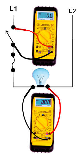
Ammeters
-
Voltmeters
-
Troubleshooting Switches
-
Troubleshooting Using a
Voltmeter
-
Systematic
Troubleshooting
-
Lineal Searching
-
Voltmeter or Ohmmeter
-
Split Searching
-
Testing Capacitors
-
Ohmmeters
-
Tips and Suggestions
Glossary
143 Pages
- 8-1/2 x 11
Soft Cover
Copyright 2012
 more HVAC/R Related
Electrical Theory
 BluePrint Reading
PLCs and Motor Controls
Electrical Menu
1930044321
|


 Add
Add 